
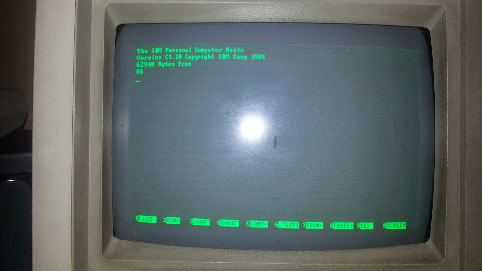
The active display area does not reach the edges of the monitor. I measure it to be about 8.75 inches by 5.5 inches. This gives an aspect ratio of 1.59 : 1. The graphics mode loses two lines and thus the aspect ratio is a sliver wider. Coincidentally, this is the square pixel ratio of CGA 320x200. There are no horizontal or vertical size or hold adjustment knobs on the monitor, only brightness and contrast. Here is a screenshot showing, somewhat faintly, the visible screen area on a 5151 :
DOSBox can take screenshots of the Hercules Graphics mode. Here is one such screenshot, untouched :

While it is a bit squashed, doubling the vertical resolution (720x696), as some Mobygames screenshots do, is just not appropriate. If you do that, you will have an aspect ratio of 1.03 :1. As you can see from the image of the real monitor, the visible screen area is not a nearly-perfect square or anything near it.
While it is not perfect, the best compromise is to increase the vertical size of a screenshot by 25% using nearest neighbor interpolation. If you resize the screenshot to 720x435, you get this result :

This gives a 1.66 : 1 aspect ratio, which is far, far closer to the ideal ratio while keeping upscaling artifacts to a minimum.
Starflight's effective resolution is 160x200, which is fairly common with older games. If you use a game that has a native 320x200 resolution, the artifacts can be a little more visible :
 |
| Maniac Mansion Enhanced Version - Original |
 |
| Maniac Mansion Enhanced Version - Resized |
 |
| Leisure Suit Larry 3 - Original |
 |
| Leisure Suit Larry 3 - Resized |
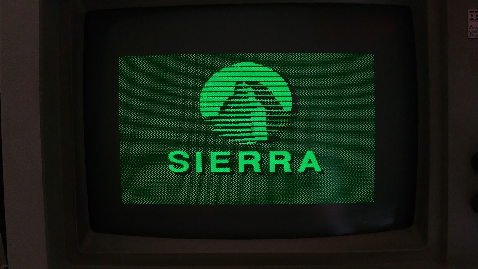
One issue to note is that most PC games use a native 320x200 resolution, and their Hercules drivers often leave noticeably large borders. Many, if not most games use double the horizontal resolution to 640 pixels, using an algorithm similar to what they would use for 640x200 CGA graphics. Starflight's effective resolution with Hercules is 640x200. The regular 16-color resolution of Maniac Mansion's graphics window is 320x128, so with Hercules they simply doubled it to 640x256. The text size remains 8x8, so there is an unused section at the bottom of the frame. Sierra did something similar with their AGI games. Their graphics window is 320x168, so with Hercules they doubled that to 640x336 and used the extra 12 lines for the status bar. Instead of keeping the 8x8 font, they used an 8x12 font unique to the Hercules driver. Typing pauses the action like SCI games, whereas it does not in all other graphics modes.
For Leisure Suit Larry 3 and other SCI0 games, the native graphics area is 320x190 in 16-color modes with the status bar taking up the remaining 10 lines. They could not double up on the graphics because they only have 348 lines to use. What Sierra did here is to increase the horizontal resolution of the whole screen to 640 and the vertical resolution to 300, effecting a 150% increase in the vertical resolution (including the status bar). Every other line is repeated. This may not give the nicest look, this was probably the simplest approach to take, which was important when dealing with taxed 8086 and 286 machines. Also, there is is no way to decrease the brightness of each individual lit pixel, so traditional filtering techniques will not work.
Here are a few more screenshots showing how non-native Hercules games fit within the screen :


Your site is so refreshing!
ReplyDeleteBy manipulating the 6845, it was possible to create a 640-pixel-wide hercules graphics mode. Have you found any Hercules games that do this, or have the majority simply centered a 640-wide line on the 720-wide graphics page?
ReplyDeleteHmmm - from the 6845's view you should be able do create a real 640-pixel-wide hercules graphics mode. But wouldn't you need another clock/bandwith to achieve the horizontal scan rate of 18.43 kHz? The standard hercules bandwith of 16.257Mhz would have been to fast, I guess. Or wasn't the 5151 at fixed line frequency?
ReplyDeleteAll IBM 5151 compatible devices use a 16.257MHz clock. This includes the Monochrome Display Adapter, the Hercules Graphics Card and the Enhanced Graphics Adapter. The EGA has a real 640x350 monochrome graphics mode, and as it uses an enhanced version of the 6845, this should be doable on a Hercules card.
ReplyDeleteMaybe this is what SIMCGA does.
Wow - thanks for your response! After writing my comment I realized that your blog post is already from February. That's why I didn't expect any reaction at all. Thanks for your cool blog, too. It was and is really fun to read- and there's still a lot to read!
ReplyDeleteAnd of course you're right: the original EGA had a clock of 16.257 MHz, too, and could be connected to an ibm5151 to show 640x350. I always guessed (!) that EGA would just show a simply centered 640-pixel-wide line on the 720-wide screen. I guessed that from the other guess that an ibm5151 should be fixed at a horizontal scan rate of 18,43 khz because of his age.And because of my information that the ibm5154 (ega monitor) had been the first monitor with variable scan rates.
If you divide the bandwith of 16.257 MHz by the scan rate of 18.43 kHz you get 882 pixels per line (720 visible). If you keep this ratio for a 640-pixel-wide screen you get a total of 784 pixel per line, which needs a 14.449 MHz clock (perhaps EGA uses the 14.318 MHz clock for 640x350 on a 5151?).
That's why I asked the question wether it is really possible to get a real 640x350 with a standard plain HGC. As far as I know the HGC had the 16.257 MHz clock fixed and couldn't use another clock. But probably I am wrong and/or my informations (out of the German book "PC Intern") are wrong.
Anyway, great blog you have! I'm really looking forward for the next entries.
(And sorry for my bad English - it's the first time I try to communicate in this language :-()
Actually I have to correct myself, a true Hercules card uses a 16.00MHz clock not 16.257MHz. IBMs cards use the 16.257MHz crystal. The relevant discussion is here : http://www.vcfed.org/forum/showthread.php?52284-MDA-Hercules-and-other-clones-what-s-the-frequency-Kenneth&highlight=hercules
ReplyDeleteI've had a close look at this image that's linked off the IBM 5151 Wikipedia page http://www.sociamedia.nl/ict/energy/ibm5151monitor.html and it looks to me like the true aspect ratio of an MDA + 5151 setup might have been 3:2. That's different from the measurements of the 5151's CRT itself, but while I don't own a 5151, all my research seems to indicate that the display didn't have H or V size controls, so the aspect ratio of fullscreen MDA text mode would have been pretty much immutable, and of course, the Hercules card's mode of 720x350 (well, minus 2, so 348) should have been the same aspect on that screen, with non-square pixels of course.
ReplyDeleteThat said, the HGC was non-IBM, and if you bought a non-IBM graphics card, you might have purchased a non-IBM display as well, and I think most of the clone manufacturers soon established the 4:3 aspect as a bit of a standard, which nearly everybody stuck to for quite some time. I think it's reasonable to say that the canonical aspect ratio for the HGC was 4:3, even though that's different from the MDA's 3:2.
PS: I've tried to check this against your MDA image as well, which is a little less straight and head-on. I've rotated it a bit and overlaid a 3:2 rectangle https://i.imgur.com/sD0iy1B.jpg , and I think your display also pretty much fits the 3:2 theory, in that the rectangle where characters are actually displayed is 3:2, though there is a little bit of, I dunno, is it the right word to say overscan to the left and to the right of that, where the electron beam is active but no actual characters can ever be displayed by the MDA. (Unless there were a way to directly hack the M6845? That would have no bearing on the notion of a canonical MDA+5151 aspect ratio though.)
ReplyDeleteAs IBM PC BASIC appears to be using all 80-columns, it would seem like the MC6845's registers in text mode will show a border on the sides. I would suggest this is the difference between the horizontal total and the horizontal displayed values of the MC6845's registers. The difference is 17 characters, but the border seems to be 2 characters on the left and 2-3 on the right. I would therefore suggest that the CRT's limits are coming into play here.
DeleteDon't forget that there's the actual sync and flyback within the blanking area.
DeleteThe screen brightness/contrast might be set up so that even with "zero" input on both video and intensity lines, there's a little bit of current going through the electron guns and so a very faint glow is caused within the active area (not uncommon on CRTs when set to give a bright image, then viewed in a dark room or with a long exposure camera).
There won't be any active output from the card's video circuitry for a certain period after the end of actual display, ie the initial hblank / front (?) porch, THEN the sync pulse happens and the beam begins to fly back, after which it starts scanning in the original direction at low speed for a period that becomes the final blanking / back (?) porch before useful output picks up again.
In the porches we will then see that glow, but during flyback we won't because the beam (even if still active) will be travelling much faster in the reverse direction, and merely add a little to the overall background which is lost amongst the lower, brighter scanning action. There isn't anything to see in the outer black areas because the beam never touches them - it doesn't "wrap around", but backtracks over the same central area.
And similarly for the vertical blanking/sync, but I think in the MDA there's essentially zero Vblank that isn't also occupied by sync/flyback (as it's slower and can be more precisely controlled), so there won't be that faint border... at least not at the bottom. Maybe some at the top.
On a more overscanned screen, like a TV, or even a VGA monitor, you don't get to see that because the entire face of it will be lit up the same as the blanking continues beyond the bezel before sync happens, and flyback takes it as far the other way. Here it would appear the beam is deliberately adjusted to underscan even in the blanking areas, which allows for quite a lot of variation (that well known bloom effect for starters) without text disappearing off the sides, even though no functional border / overscan / bleed area / text-safe zone is utilised. It's a terminal, not a broadcast video monitor, so that sort of thing isn't necessary.
(agh, out of space)
(cont)
DeleteSomewhere around here I had the Herc CRTC specs (wanting to check some other detail about possible interlacing and wacky Vsync rates in 640x400 modes is how I ended up here in the first place)... let's see...
Htotal is 61h, Hdisp is 50h, Hblank starts at 52h? (= where H*sync* starts?), and Hsync width is 0Fh. All defined as character spaces, and Htotal needs to be +1 vs what's actually in the register (and maybe the sync width?).
(This seems to be congruent with the MDA, to the extent that the different pixel clock causes lower H+V sync rates; the 90-column and graphics modes diverge somewhat)
So, that's 98 total characters per scanline, and 80 displayed. Of the leftover 18, 15 (16?) are occupied by sync pulse, leaving two blank after the end of each active period of the line, and a nominal one-character (zero?) blank before the start of the next (though whether the monitor holds at the start position until the pulse drops, or just starts running again as soon as it finishes flyback, who knows). Which is *partly* in line with a guideline mentioned elsewhere that FP, sync and BP should be in a 1:2:2 ratio (here it's 2:15:1 instead... or 2:16:0?).
In which case, that corresponds more or less with what's observed. The monitor doesn't respond absolutely immediately to the start of the sync, and perhaps needs at least another character time (approx half a microsecond) to trigger the flyback. Which then takes a little less time to complete than the actual length of the sync pulse, allowing the horizontal trace just enough time to stabilise before video starts being sent down the line again.
Vertical total is 19h (+1), or 26 rows, with a 6-line remainder tacked on. Active area is 25 rows, leaving us just 20 lines in which to complete the retrace. V"blank" (sync) is defined as happening right after the 25th active row, with no width given (the CRTC presumably has a certain default Vsync width, maybe one character row, or perhaps 16 lines, both of which specs sound vaguely familiar). If there's not really any remnant glow visible above or below the active text area, we can assume that vertical retrace kicks in quickly enough that the beam doesn't even make it out of horizontal retrace before beginning its ascent, and is either held stationary at the top of the screen until the first row starts output, or it only just makes it there in time and resumes normal downwards tracking somewhere in the final Hsync flyback (which will continue cycling during the vsync).
(3/3)
Delete...though, zooming back in on that imgur file, there seems to be at least a half character row of background glow above the first line with text on it, if not a full one. If we assume the title and copyright info are printed right at the top of the normal text window, then it would appear flyback only takes maybe ten horizontal scans worth of time, after which the beam starts tracking normally, waiting for some kind of signal to activate it properly.
So we could, with enough memory address range, probably push the visible area out to maybe 85 columns by 26 rows and still have it all be readable, with perhaps a slight alteration to the sync position/width or Htotal, and a few extra lines added to the Vadj register, slowing the scan rates by a tiny amount but unlikely enough to cause a problem. The text then just kissing the very edge of the background fuzz area (overspilling it would be an issue due to lit pixels being smeared across the retrace area, or at least being overly bright where they're mushed together right on the edge). With a true MDA clock, the syncs may not even slow down as much as they do for stock MDA-equivalent Hercules modes, which are still well within the alterations needed for 640x400 (that still seems 5151 compatible?!).
If the actual scanning circuitry (and the user's eyes) can withstand the necessary reduction in sync rate, those limits can be extended a good bit further still, though I'm not yet sure whether 400 lines (so the equivalent of 28.6 text rows) would fit the vertical space. Possibly an increase in Hsync rate could squeeze them in a bit tighter, but, paradoxically, the only settings I've found for 640x400 actually *widen* the lines and reduce the Hsync, to less than 18.0kHz... (and maybe use interlace instead of progressive, so have to try and impose a vertical stretch to keep everything from looking totally misshapen). I sort of thought CRTs were typically a little more tolerant of faster syncs vs spec than they were lower ones, especially in the horizontal, but maybe that's mistaken?
Just to go back to the question of "centering a 640 pixel image within a 720 frame" - that wouldn't have been necessary. It would have been fairly trivial to reprogram the CRTC (as EGA mono does by default), especially as Hercules has no BIOS and demands that all software using its graphics (or 90-column text mode, which cuts the font width to 8 pixels instead of 9) directly sets it up anyway. In this case, changing the "Horizontal displayed" figure from 45 blocks (of 16 pixels) to 40, leaving the "Horizontal total" unchanged, then tweaking the sync position and/or width as required to shift the image roughly 40 pixels to the right along the line (though 32 or 48 might have been close enough, should it only be doable in blocks of 16).
ReplyDeleteUsing the motherboard's NTSC colourburst clock may well have been an alternative (it'd give somewhere from 634 to 644 pixels in the space of the original 720, depending on the card's actual oscillator), but by all accounts it doesn't seem to have been a thing. Users were well accustomed to dealing with images that didn't reach the edge of the display anyhow, and it would have been much more complication than just changing a couple of bytes during the video mode setup (...well, OK, it would really have meant a few more register changes, but that's still extra work and, as it'd almost certainly change the scanrate by a certain amount, possible risk, not to mention totally confusing the average LCD encoder in portables). Plus I have a feeling that clock wasn't even accessible / connected at all on the MDA or Herc, and even if it was, clones may well have not bothered with it, meaning Bad Things could happen if you tried to select it (complete card crash from not having a clock, simply sticking with the 16MHz clock and thus overdriving the monitor until it smoked, etc). Safer, easier, and more reliable just to go with the option that gave a slightly squished image. Besides, that way, the pixels were actually a little closer to the expected aspect ratio, rather than being stretched even further away from it.