
The BIOS Modes
Mode 00h - 40x25 B&W
Mode 01h - 40x25 Color
Mode 02h - 80x25 B&W
Mode 03h - 80x25 Color
Mode 04h - 320x200 Color
Mode 05h - 320x200 B&W
Mode 06h - 640x200 B&W
On an RGBI monitor, the identical Color/B&W modes have no distinction except in Modes 04 and 05. On a color composite monitor or TV set, color modes enable the color burst and b&w modes disable the color burst. The IBM PC defaults to the 40x25 or 80x25 B&W modes depending on how you set a dipswitch. Text, especially 80-column text, is much more difficult to read on a composite color display.
The CGA card has 16KB of RAM. A full screen of 40-column text required 2KB of memory, allowing for 8 separate pages. A full screen of 80 column memory required 4KB of memory, allowing for 4 separate pages. Graphics modes took up all the 16KB of memory. In order to really put the CGA card to work, one has to go deeper and look beyond the BIOS and what could be done by accessing its registers directly.
Hardware Registers
03D4 - MC6845 Address
03D5 - MC6845 Data
(Described below)
03D8 - Mode Control Register (Write Only)
Bit 0 - 0 = Selects 40x25 Text Mode, 1 = Selects 80x25 Text Mode
Bit 1 - 0 = Selects Text Mode, 1 = Selects Graphics Mode
Bit 2 - 0 = Selects Color on Composite Display, 1 = Selects B&W on Composite Display
Bit 3 - 0 = Disable Video Signal, 1 = Enable Video Signal
Bit 4 - 0 = Selects 320x200 Graphics, 1 = Selects 640x200 Graphics
Bit 5 - 0 = Blinking Enabled, Character Cell can Select from 8 Background Colors, 1 = Blinking Disabled, Character Cell can Select from 16 Background Colors
03D9 - Color Select Register (Write Only)
Bit 0 - Selects Blue Color of Border (Text Modes), Background and Border (320x200 Graphics) or Foreground (640x200 Graphics), 0 = No Color, 1 = Color
Bit 1 - Selects Green Color of Border (Text Modes), Background and Border (320x200 Graphics) or Foreground (640x200 Graphics), 0 = No Color, 1 = Color
Bit 2 - Selects Red Color of Border (Text Modes), Background and Border (320x200 Graphics) or Foreground (640x200 Graphics), 0 = No Color, 1 = Color
Bit 3 - Selects Intensified Color of Border (Text Modes), Background and Border (320x200 Graphics) or Foreground (640x200 Graphics), 0 = No Color, 1 = Color
Bit 4 - 0 = Selects Non-intensity Palette Colors, 1 = Selects Intensity Palette Colors
Bit 5 - 0 = Selects Palette Color Set 1, 1 = Selects Palette Color Set 2
Bit 0 - Display Active, 0 = Display Active, 1 = Display Inactive
Bit 1 - Light Pen Trigger, 0 = Trigger Active, 1 = Trigger Inactive
Bit 2 - Light Pen Switch, 0 = Switch On, 1 = Switch Off
Bit 3 - Vertical Retrace Active 0 = No, 1 = Yes
03DB - Clear Light Pen Latch
03DC - Set Light Pen Latch
(Any access to these registers activates the function of these registers)
A light pen is connected to a six-pin header on the CGA card. A light pen consists of a photo sensor and a switch. The idea is that when you touch the pen to the screen and pushed the button, the system will know where you touched the screen and react to the input in some way. The way this works in hardware is as follows :
1. Clear then Set the Light Pen Latch, this allows the MC6845 to obtain the position of the light pen.
2. Poll Bits 1 and 2 of 03DA, if both are 0, then that means that the light pen was pointed at some portion of the screen
3. Find out which memory address the pen pointed to by reading R16 & R17 of the MC6845.
4. Repeat
Light pens can work in all text and graphics modes, but the precision may not be what you would like.
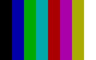
RGBI Colors

The CGA can display 16 colors on a TTL or "Direct Drive" RGBI monitor. However, it can only display all of them at one time in text modes. The colors are encoded as 4-bit binary values, with one bit available for red, green, blue and intensity.
IRGB
0000 Black
0001 Blue
0010 Green
0011 Cyan
0100 Red
0101 Magenta
0110 Brown (sometimes Dark Yellow)
0111 Light Gray
1000 Dark Gray
1001 Light Blue
1010 Light Green
1011 Light Cyan
1100 Light Red
1101 Light Magenta
1110 Yellow
1111 White
Resolutions and Palettes
The BIOS can select between three color sets in 320x200 resolution modes :

Mode 04 Color Set 1
0010 Green
0100 Red
0110 Brown

Mode 04 Color Set 2
0011 Cyan
0101 Magenta
0111 White

Mode 05 Color Set
0011 Cyan
0100 Red
0111 White
The BIOS cannot turn on the intensity bit, you must write to 03D9. Mode 05h was never documented by IBM as giving different colors on an RGBI display. You cannot change the Color Set in Mode 05h, but you can set the intensity. So when you add intensity, you get :

Mode 04 Color Set 1
1010 Light Green
1100 Light Red
1110 Yellow

Mode 04 Color Set 2
1011 Light Cyan
1101 Light Magenta
1111 High Intensity White

Mode 05 Color Set
0011 Light Cyan
0100 Light Red
0111 High Intensity White
Given the nibble values, you can see that the difference between Color Set 1 and Color Set 2 is the activation of the Blue bit. In Mode 05h, it appears that the Blue bit is always activated except for the middle color, where it is never activated. The pattern suggests that bit 2, when set to 1, from 03D8 is ANDed with the Green bit from the Color Set and put in the Blue bit, essentially giving the proper nibble pattern shown above.

In the 640x200 graphics Mode 06, only two colors were available. The BIOS gave a default foreground color of White. The background and border colors in this mode are always black and cannot be changed with a standard CGA card. The foreground color can be changed to any of the 16 colors in the CGA palette, but this could not be done by the BIOS.
The Motorola MC6845
The CGA is at heart a text-based display adapter. It uses the MC6845 Cathode Ray Tube Controller (CRTC) for setting up the display and most display timings. This chip is also used in the text-only Monochrome Display and Printer Adapter. The chip acts in terms of scanlines and character cells, so how did IBM manage to coax medium and high resolution resolution graphics modes? How did programmers coax low resolution full color modes?
This chip has eighteen internal registers, and the register you wish to access is loaded by writing the Address Register number to 03D4. The data to be written to that Address Register is written to 03D5.
Here are the registers and their default IBM PC BIOS values :
| Address Reg | Reg # | Unit | Read/Write | Reg Name | Reg Size | 40x25 Alpha | 80x25 Alpha | Graphics |
| 00 | R0 | Char | Write | Hor. Total | 8 | 38 | 71 | 38 |
| 01 | R1 | Char | Write | Hor. Disp. | 8 | 28 | 50 | 28 |
| 02 | R2 | Char | Write | Hor. Sync Pos. | 8 | 2D | 5A | 2D |
| 03 | R3 | Char | Write | Hor. Sync Width | 4 | 0A | 0A | 0A |
| 04 | R4 | Char Row | Write | Vert. Total | 7 | 1F | 1F | 7F |
| 05 | R5 | Scan Line | Write | Vert. Total Adj. | 5 | 06 | 06 | 06 |
| 06 | R6 | Char Row | Write | Vert. Disp. | 7 | 19 | 19 | 64 |
| 07 | R7 | Char Row | Write | Vert. Sync Pos. | 7 | 1C | 1C | 70 |
| 08 | R8 | Write | Interlace Mode | 2 | 02 | 02 | 02 | |
| 09 | R9 | Scan Line | Write | Max Scan Line Addr. | 5 | 07 | 07 | 01 |
| 0A | R10 | Scan Line | Write | Cursor Start | 7 (5) | 06 | 06 | 06 |
| 0B | R11 | Scan Line | Write | Cursor End | 5 | 07 | 07 | 07 |
| 0C | R12 | Write | Start Add. (H) | 6 | 00 | 00 | 00 | |
| 0D | R13 | Write | Start Add. (L) | 8 | 00 | 00 | 00 | |
| 0E | R14 | Read/Write | Cursor Add. (H) | 6 | XX | XX | XX | |
| 0F | R15 | Read/Write | Cursor Add. (L) | 8 | XX | XX | XX | |
| 10 | R16 | Read | Light Pen (H) | 6 | XX | XX | XX | |
| 11 | R17 | Read | Light Pen (L) | 8 | XX | XX | XX |
The text character cell in all CGA modes is 8 pixels by 8 scanlines. This gives an effective resolution of 320x200 for the 40x25 text mode and 640x200 for the 80x25 text mode.
From the numbers given in the table, we can make calculations.
From R0 and R1, we know how many horizontal characters are displayed.
R1 - The total number for the 40x25 mode, 38h/56 characters + 1 character if you include the border.
R2 - Of those, the displayed number is 28h, or 40 characters. This works similarly for the 80x25 text mode.
R3 and R4 deal with Horizontal Sync. Horizontal Sync starts at Character 45 or 90 and the Width of the Sync lasts for 10 Characters. When some games allow you to adjust your display by shifting the image to the left or right, they are almost certainly writing to R3 and R4.
Next we go to the vertical timings
R4 and R5 deal with the total characters displayed vertically. We have 1Fh/31 + 1 characters displayed by R4. Given an 8x8 text box, this gives us 256 scanlines. The total number of scanlines in an NTSC display in a progressive scan mode is 262, so R5 gives us the extra 6 scanlines.
From R6 we always get 19h/25 rows of text characters.
R7 gives us the time for the vertical sync signal, and it starts at character 1Ch/28.
For Graphics Modes, things are a little different by the vertical. Here we have a vertical displayed total R6 of 64h/100 "character rows" and a vertical total R4 of 7F + 1 or 128 "character rows". Here is where the famous CGA interlaced memory model comes into place. The graphics modes have 200 lines, so they are programmed as two 100 line pages by the 6845's perspective. Each line is separated by 8KB of memory in an interleaved format.
R8, the Interlace Mode register, is never intentionally used because it does not display a proper interlaced signal with a standard monitor.
R9 tells us how many scanlines there will be for each character row + 1, so you get 8 scanlines for text modes. For graphics modes, this value ends up being 2. Combined with the values at R4-R6, this gives you the interlaced memory addressing. Using this value for the 80x25 text mode gives you an effective 160x100 mode when using the ASCII character 221 for every text box.
R10 and R11 allows a cursor of up to 32 scanlines, and bits 5 and 6 of R10 control the blinking rate for the cursor.
R12 through R17 are programmed in terms of memory addressing. Each pair of registers combines into a 14-bit value. Essentially this means the MC6845 can address 16,384 bytes of memory. In text mode, you can obtain eight pages of 40x25 text and four pages of 80x25 text. Graphics mode takes up all the memory. The Start Address can come in handy for hardware scrolling and double buffering.
One thing the MC6845 does not determine fully is how many pixels there are on a line. This is determined by the dot clock rate. In 320x200 and 40x25 text mode (which has the equivalent resolution), a 7.16MHz dot clock is used.
First, we divide 7,159,090Hz by 60Hz to obtain the number of pixels for each frame = 119,318.1667
Next, we divide 119,318.1667 by 262 lines to obtain the number of pixels per line = 455.4128
455 is larger than 320, so this doesn't make sense. However, that is the total number of pixels displayed per line, including both active and border portions of the screen. Dividing R2 by R1 gives us an active to total ratio of .70175. Now, 455 * .70175 gives us 320 pixels (more or less).
It follows that the 14.318MHz dot clock is used for the 80x25 text and 640x200 graphics modes. Even though both use this dot clock, there is random flickering lines if you write to the 80x25 text mode outside vertical retrace. This is the dreaded CGA snow. Snow is the result of the CPU and the MC6845 accessing the memory at the same time. The CPU must win the fight or you lose access to the data. The MC6845 shows random lines in the character cell which is being written to during that frame. In 40-column text and the graphics modes, the CPU writes and the MC6845 reads are properly synchronized to avoid snow, but the 80 column text mode's memory bandwidth requirements are too high.
DOS updates 80 column text in a slow and flickery fashion because it can detect a CGA card and tries to avoid snow. IBM did not assign an IRQ to its video adapters until the PCjr. and EGA, so there is no interrupt alterting the programmer that the system has entered a retrace period where it is safe to write to the screen memory. Instead the programmer must routinely 3DA for the appropriate time. Polling is slower than interrupts. Alternately, using the BIOS functions to address the screen would avoid snow, but was also slower than dealing with snow.
"Alternate Palettes"
If you bought an IBM PC with a CGA card in it when it was first made available on August 19, 1981 or for some time thereafter, you would need to find a compatible monitor from a source outside of IBM. The monitor you purchased may only have been able to display one of these 8-color palettes :
IBM recognized in its first IBM PC Technical Reference Manual that some of the available RGB monitors could not handle the intensity signal or display a brown color. If you use a "CGA" to VGA converter these are the colors you can expect if you do not have a proper digital RGBI to analog RGB converter circuit.
Adding Intensity is easy enough, but if you monitor does nothing else, this is the palette you will get :

Color #6 is dark yellow in this palette, but the IBM canonical color is brown. The difference between dark yellow and brown is that the green signal is halved. So, if Red is 1, Blue is 0 and Intensity is 0, then Green's analog component will be half as bright.
Brown is the color that will be displayed on IBM's official CGA monitor, the 5153 Color Display, and its later color monitors. It will be the color displayed on the PCjr., Tandy 1000, EGA, MCGA and VGA adapters.
The Commodore 128, in addition to containing a C64 compatible VIC-II video chip, also includes a text-only MOS 8563 Video Display Processor. This chip officially provided an 80-column text mode using an 8x8 pixel based text cell size and could display up to 16 colors. Those colors and the digital method of their display are identical to the IBM CGA card. Like IBM, Commodore treated color 6 as brown, not dark yellow The Commodore 128 monitors and the Amiga monitors that support TTL RGBI will show a proper brown. For more information on the C128's development, start by reading the article here : https://www.commodore.ca/commodore-products/commodore-128-the-most-versatile-8-bit-computer-ever-made/
Interesting! I understood that the "four" palette options were determined by fixing the B and I bits and letting the bitmap adjust the R and G bits, but I never understood why the background color was freely selectable. Now I know how the color register works.
ReplyDeleteBut now I wonder: with eight bits available in the color register, why did IBM make the decision to arrange it like this? Why not, for example, have two freely selectable colors (foreground and background in 640x200 mode), and have the other two colors in 320x200 mode always be white and black?
Cyan/red/white/black is a good non-garish colorblind-friendly palette, with others optimized for contrast (blue/yellow/white/black) or a setting-appropriate theme (blue/green/white/black for ocean, red/magenta/white/black for cyberpunk, green/magenta/white/black for Apple II ports, etc.) To say nothing of just having a 16-bit color register to make all four colors freely selectable...
IBM used discrete logic for the CGA Registers, there are no custom chips on the board. The chips used were 74LS174s, which are 6-bit latches/flip-flops. So they simply did not have the extra 2-bits to use. With the PCjr., they used an ASIC chip that could perform all the functions of the discrete logic chips on the CGA card and more like implement palette registers for a fully-selectable 16-color palette in most of the graphics modes. Of course the way they did this was not register compatible with CGA for the most part, something Tandy fixed in its implementation.
ReplyDeleteA nice rundown, I'd just like to suggest a correction to how the timing is arrived at. You don't start from the framerate and work upwards; in fact, CGA, like a lot of other nominally TV-compatible computers, *doesn't* create an absolutely NTSC standards compliant signal. All the 14.318MHz colorburst crystal does is guarantee that you get a TV / regular composite color monitor compatible signal encoding, so the screen can understand what colour you're trying to send to it.
ReplyDeleteThe CRTC can only work in terms of whole character widths (thus, in this case, blocks of 8 pixels) for the line length, and - as it doesn't support interlace mode - whole lines to form each frame (also each field, as they're the same as each other in progressive mode). Therefore all you can produce is an as-close-as-possible scan rate and hope the receiving screen is flexible enough to sync to it (which, in fairness, most are; in fact you can usually expect a typical composite / RGB monitor, and some TVs, to sync to a much less standards-compliant signal than CGA).
The Amiga manages exact NTSC sync (in interlaced mode at least) using its custom chipset, where it allegedly counts exactly 455 pixels per line (actually, alternates between 454 and 456 to force the color clocks to align line-to-line, but it averages out to the exact 455 pixels - or 227.5 x 3.580MHz NTSC color-clocks - needed for standards compliance), giving us a guide for what CRTC settings to use. Happily, 456 divides cleanly into 8, and is less than a quarter of a percent adrift from standard. Using the halved 7.159MHz clock, or the full rate with 912 pixels per line (57 or 114 character-times, which we can verify from the register settings - convert from hex to decimal, then add one), we get almost exactly 15.700kHz, only a little below NTSC's 15.734kHz, and above the 15.625kHz of PAL which most monitors will also happily sync to.
The vertical side of things is a little trickier to calculate, but what matters for the moment is that it comes out to 262 lines (vs 262.5 per field standard, ie 525 per interlaced frame), with the slightly longer lines but slightly fewer of them cancelling out to give almost the right refresh rate: 59.923Hz, vs 59.940Hz standard, a difference of less than 1/30th of a percent.
With the dot clock frequency and the register settings you can use that method to work out the line-scan and frame-refresh rates for any CRTC-using (or CRTC-alike) graphics system. For example, the MDA uses a 16.257MHz clock, 98 characters of 9 pixels each (= 882 pixels total) per scanline, and 370 total scanlines (with a 720x350 active area), for a 18.432kHz scan rate and 49.816Hz refresh.
((hit the 4096 character limit, ironically))
((follow-on))
ReplyDeleteThe relationship between R1 and R2 is fairly meaningless, unless you're trying to come up with a screen mode on different hardware to work with a monitor primarily designed to run with one of these systems, and want to know what proportion of each line is occupied by active image data (e.g. for CGA it's about 70.2%; VGA uses 80.0%, MDA 81.6%, and EGA 86.0%) so you can either figure out how many pixels you might be able to actually see after determining a compatible scan rate, or to figure out a suitable dot clock (and total pixel count) to produce a certain number of visible pixels. Even so, what's more useful is just the "active characters" count proper (multiply by character width for the active pixels, then divide by dot clock MHz to get active width in microseconds), the total count (full line width in usec), and the former *subtracted* from the latter (which gives us the blanking width / flyback time, in pixels and usec, usually with a certain amount of underscan; there is a way to work out what the full overscan, ie coloured border width, is from the registers, but I forget exactly what - probably involving sync position and width?).
And the same for vertical active vs vertical total... where the 200 lines out of 262 for CGA is again pretty conservative (VGA only leaves 45 spare lines out of 525, MDA 20 out of 350, and the extremely edgy EGA just 16 out of 364~366), but for the same reason as the horizontal - it allows the use of cheaper, wider-tolerance hardware and guarantee that the whole active area will still be visible on all units, just with a rather variable amount of border (later monitors were more expensive and rather more finely specified...).
Working it back from your desired scan rate is only really useful to get a guide figure for what the actual settings need to be. Unless you have particularly fancy display hardware, or deliberately tune the dot clock quite finely (without bothering about e.g. colorburst compatibility) you generally can't hit the target rate exactly and will just have to settle for the closest that a single-character granularity (for PC and other CRTC machines; or one memory-word-time on the ST range = 4 to 16 pixels depending on resolution; or one actual NTSC color clock / half a clock average on the Amiga, or about twice / four times the ST grain) and nearest-line per frame counts (or line-plus-a-half per field in interlace) can get you...
Oh, and of course, there's a seventh colour palette: 320x200 output to a composite screen with the colour turned off. Which gets you Black, white, and two greys... the equivalent of the cyan and light red. Not sure if it goes black-light-dark-white, or converts the middle colours opposite to how you'd expect though.
ReplyDeleteI think your registers port numbers may be incorrect. I was writing a program in which part of the routines to setup the graphics involved switching the palette. I wrote to register 0x03D8 (what you state is the color register) but the screen went black, instead of the pixels having a different color. I did some more research, and and on another website it says that 0x03D8 is actually the mode register.
ReplyDeleteAccording to your blog 0x03D8 is color register and 0x03D9 is mode register, but this other site said 0x03D8 is mode register and 0x03D9 is color register. It seems that this second definition is correct, as it works at least in DosBox. I don't have real hardware to test it on though.
Sorry about that, I had the register order switched. I have fixed it.
DeleteGreat article, what instance which register values would I need to setup a 192x168x4 bitmap screen? I have been trying but I haven't had much success. Thanks
ReplyDelete